CONAR RECEIVER MODIFICATIONS !!!
"....a face only a mother could love."
Fullwave Bridge Rectifier
This mod removes the single diode and replaces it with a full wave bridge rectifier.
Of all the modifications you can do to the Conar - this one is the most important because it removes the obnoxious AC hum from the speaker. As you recall from our previous discussion on the power supply, the cause of AC hum is the use of ONE diode to rectify the AC voltage. Clearly, what is needed is a fullwave rectifier consisting of 4 diodes to produce a better filtered 120 cps DC pulse. One could buy and put together a bridge or you can purchase one already assembled. Here is the one I purchased for $0.79. It is 600 PIV and is capable of 4 amps. This is way overkill for this application but the reason I bought it was that it has fairly stiff leads that will be used to support the power transformer wires. For $0.79 you can't go wrong.
Lets take a closer look at our bridge rectifier.
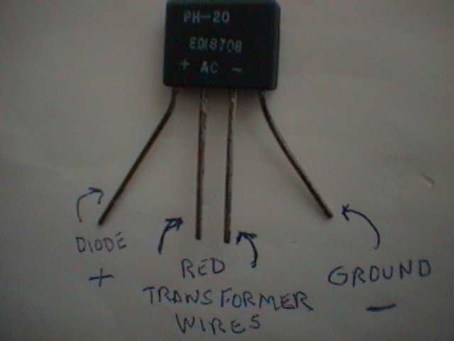
As you can see, it has 4 leads. The center two go to the AC power transformer wires (which are red). The negative side on the right goes to ground as you would expect. The positive lead on the left goes over to the present diode's positive side.
FIRST UNPLUG THIS DEVICE FROM THE WALL SOCKET !!!
Next, strip the chassis from the enclosure box. Then flip it over so that the rear of the receiver is facing us. The power supply section will be to the rear on the left side. Right at the terminal strip where the AC power cord comes into the chassis.
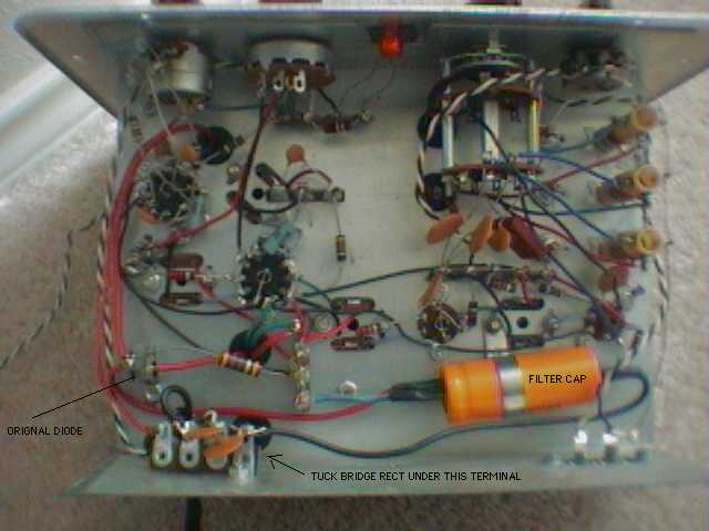
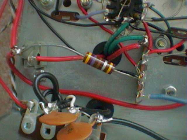
Here is a closeup view. Notice 2 red wires coming from the black plastic grommet in the center? One side goes to the ground lug. The other one goes to one side of the diode D1. We will have to cut this wire and place the new positive lead from the bridge rectifier on the other side of D1 which is also connected to the resistor R3 (470 Ohms 1 watt)
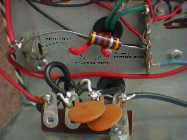
Cut and remove the red transformer wire from the diode. Now cut and remove the red transformer wire from the ground lug and slide it under the resistor R3 as shown below.
Now we are ready to install the bridge. Flip the bridge rectifier so that the Positive lead is on the LEFT side. Slide it under the 120 VAC terminal strip as shown below. Bend the Positive lead and solder it to the side of diode D1 that is also connected to R3. Now carefully bend the Negative lead on the right side and solder it to the ground lug on the 120 VAC terminal strip as shown below. Might sure that the bridge rectifier body can not move. Now solder the two red transformer wires to the center leads of the bridge rectifier's body. Re-arrange or shorten the leads to reduce the possiblity of shorting the power transformer. The leads are very stiff. To increase safety, you can use some heat shrink tubing or electrical tape if you feel the need.
- WARNING -
CONAR did not place any fuses, fuselinks or breakers in this product !
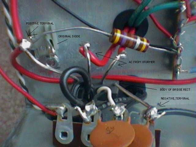
Now, triple check your work!!!
Make sure everything is safe and good to go!
Think Safe - Act Safe - Be Safe
This completes the bridge rectifier modification. Next step is to beef up the power supply filters.
Go Back to Main: MODIFICATIONS page
Go Back to Main: CONAR page
Conar Transmitter Manual - and - Conar Receiver Manual