CONAR RECEIVER MODIFICATIONS !!!
"....a face only a mother could love."
Power Supply Filter Modification
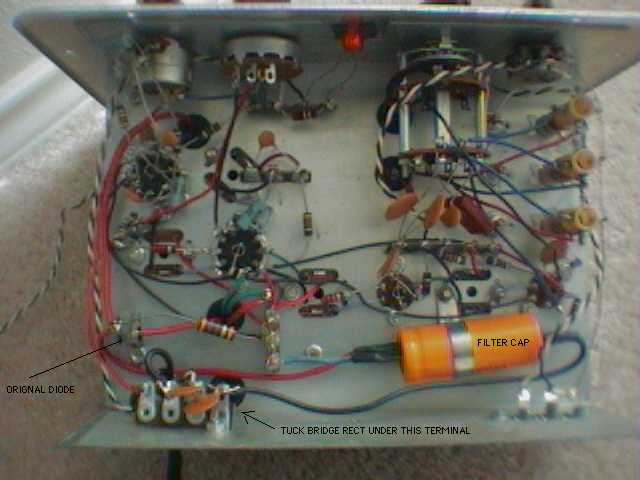
This modification adds two more filter capacitors to the power supply circuit.
The stock power supply circuit can use some more filtering to reduce the amount of AC hum heard over the speaker. This can be done by adding a capacitor in parallel to the stock capacitor. Doing so will increase the amount of capacitance and thus the amount of filtering.
I purchased two radial type elctrolytic capcitors with a value of 100 mfd and a working voltage of 200 VAC for $0.79 each.

First locate the filter capacitor. In an unmodified CONAR receiver, it is the large orange tube at the bottom of the picture. This capacitor actually contains two capacitors, a 50 mfd and a 30 mfd. Notice the black Negative wire is attached to a ground lug.
Take one of your new purchased electrolytic capacitors and solder the NEGATIVE lead to ground. Now solder the positive lead to the terminal connected to the blue wire coming from the original filter capacitor.
Double check your work!!
Take the other purchased electrolytic capacitor and solder the NEGATIVE lead to ground terminal lug - or - to the Negative lead of the capacitor you've just soldered (which ever is easiest).
Now solder the Positive lead of your new capacitor to the side of the diode D1 connected to resistor R3 (470 Ohm 1 watt). If leads are not long enough, you may just solder the capacitor lead to the diode side of resistor R3 leads.
Now, Triple check your work!!!
Make sure everything is safe and good to go!
Think Safe - Act Safe - Be Safe
You are now ready to power up your CONAR Receiver. Plug the AC plug into the wall socket and turn on the receiver via the power switch in the Volume control. You should wait for a few seconds of warm up. You will IMMEDIATELY notice little or no AC hum.
You may be tempted to tune in signals at this point.
You are not ready yet, young grasshopper...
More than likely, the previous owner had tried "everything" to tune in a signal and chances are pretty good that he tried to tweak the coil slugs at random in a desperate attempt to get it to work. I have worked on three of these things and all of them were horribly miss-aligned.
Before going further, I recommend you re-align your CONAR based on instructions given by the manual. I highly recommend you use the alignment procedure utilizing the multimeter. The 455 kc IF coils are very sensitive and there is no way you can get a good alignment by ear. If possible, beg or borrow a good rf generator with 455 kc. It will make the alignment go faster if you have the right tools before you start.
Go Back to Main: MODIFICATIONS page
Go Back to Main: CONAR page
Conar Transmitter Manual - and - Conar Receiver Manual