


In the world of wireless, as in any other spheres of technical interest, there will always be from time to time apparatus which has a "novelty" appeal. There are, no doubt, readers who are essentially very practically minded and who have no time for novelties, whereas some other readers will delight in such circuitry.
Any magazine or editor, is faced with the constant and very difficult problem of trying to accommodate all tastes, and in presenting this month's blueprint it is felt that both these two groups will gain a measure of satisfaction. The novelty enthusiasts because it is shown how to build an amateur transmitting station-transmitter, receiver and frequency meter on a chassis which measures only 3-7/8 in x 2-3/8 in. x 9/16 in. complete with valves. This unit is thus small enough for the over-coat pocket and requires only a very modest power source to get on the air. Indeed, the power supply from the average domestic valve receiver will suffice.
The practically minded or the more serious reader will find this project of interest since it presents a transmitter and receiver which is efficient and will take up hardly any room at all. It can be used as a standby rig and/or a crystal frequency meter to provide accurate calibration from 1-30 Mc/s. Miscellaneous crystals may be tested with it and if the appropriate crystals and coils are inserted it could prove most useful for 160 metres where there is a maximum of 10 W anyway.
Most QRO rigs for 3.5 - 28 Mc/s present a problem when trying to use them on top band because a great deal of power has to be lost. If the big rig runs 150 W, then some means of "losing" 140W is required and the usual practice is to construct a separate TX (transmitter) for Top Band (160m) - (NOTE: British amateurs are only allowed to run 10 Watts on 160m!) This article describes the construction of just such a rig with the minimum number of components consistent with reliability, together with simple uncomplicated circuitry.
For others this unit might prove very useful to take on holiday. In such an application as this, a companion midget power unit might be constructed using a TV preamplifier type double-wound mains transformer together with a couple of silicon diodes.

THE TRANSMITTER SECTION
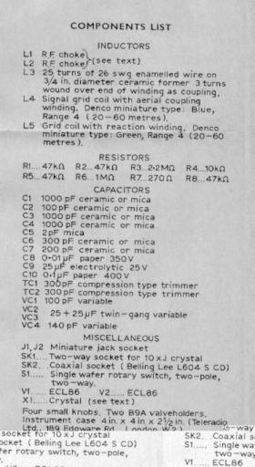
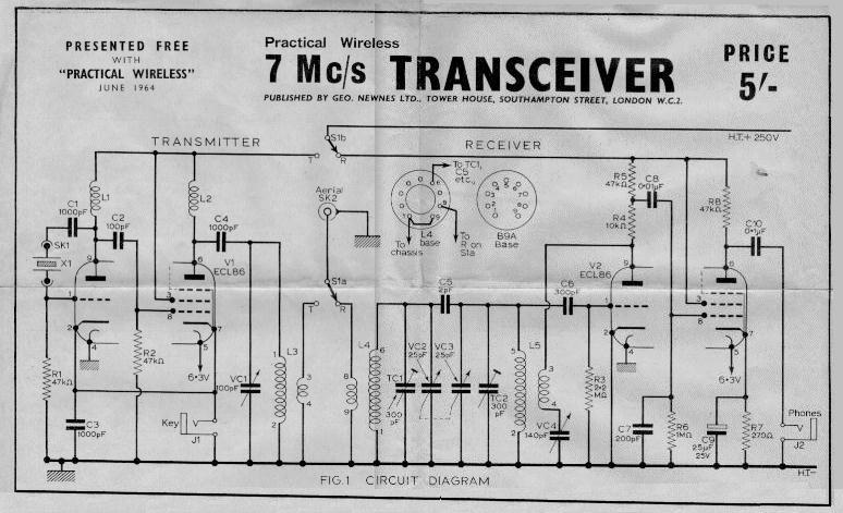
The transmitter consists of a Pierce crystal oscillator operating on 7 Mc/s followed by a pentode power amplifier also tuned to 7 Mc/s. This circuit configuration (See Fig 1 on Blueprint) is chosen so as to use the minimum number of components consistent with reliable performance. NOTE that the ECL86 is the same as a 6GW8 tube in the USA.
Now to consider the circuit in some detail. C1 is used mainly to isolate the crystal X1 from the h.t. (B+) line. Some constructors may point out that circuits do exist which do not use a capacitor at all in this position, but this would have meant that the crystal socket pins on the front panel were live ("hot") with respect to the case, and C1 was included to avoid this. R1 provides the necessary bias for the triode portion of V1 and L1 is an r.f. choke anode load.
C2 performs the usual role of coupling capacitor, passing the generated signal to the grid of the p.a. (power amplifier) stage, and also serves as a blocking capacitor. R2 provides the necessary bias for the pentode section and the actual bias voltage is obtained from the signal itself. Using this method of biasing means that the p.a. must be keyed, otherwise when there is no signal there will he no bias and the p.a. will immediately start to draw excessive current.
It would, of course, be possible to place a resistor-capacitor combination in the cathode of the p.a. in order to limit the current under no-drive periods, but this would have meant two extra components plus a slight loss of power.
It was also necessary to key the c.o. (crystal oscillator), otherwise it would block the receiver if left running. Since. however, the h.t. (high tension = B+) is switched from transmitter to receiver, it would be in order to take the cathode of V1 triode directly to earth and key only the pentode section if so desired. Should this be done, it might also be an idea to plug a modulator into the key socket thus using cathode modulation of the P.A.
As this form of modulation is in the "efficiency class", only a very small amount of audio power would be required.
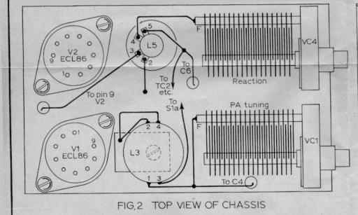
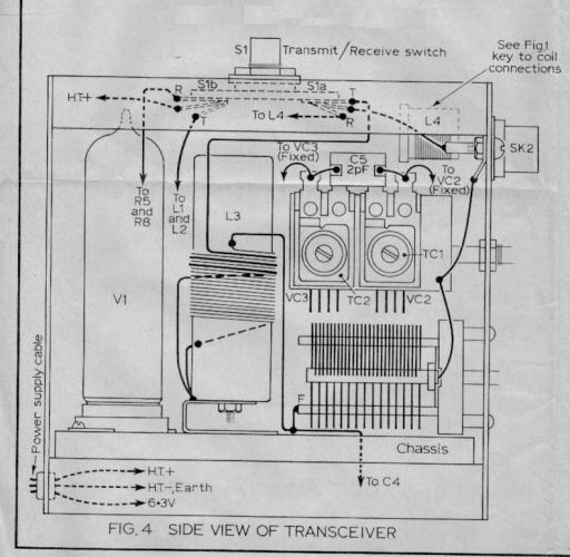
The inductor L2 functions as an r.f. choke and C4 as a blocking capacitor to prevent a short between h.t. positive and earth via L3. VC1 and L3 form a tuned circuit resonant at the transmitting frequency.
It would have been in order to place the tuned circuit in the anode lead to the pa. thus eliminating C4, but the spindle of VC1 would then be at h.t. potential and this was considered undesirable.
ADDITIONAL BLUEPRINT PICTURES:
|
|
|
|
THE RECEIVER SECTION
There is nothing startling or new about the receiver, indeed one old timer on seeing it remarked that apart from the size it was pretty much the same as his main station receiver back in the 1920s. However, with the use of modern high gain valves, today's O-V-l circuit can prove lively and efficient. The receiver, therefore, consists of a triode detector followed by a pentode audio amplifier.
The triode section is a regenerative detector complete with the normal tuned grid circuit and grid leak Ra, with VC4 acting as the regeneration control. R4 and R5 are anode load and decoupling resistors, the capacitor C8 passing on the signal to the pentode grid.
C7 is used to provide an "easy" path to earth for any residual r.f. which may have ventured thus far. R7 and C9 are the usual bias components common to many audio stages and R8 forms the anode load of the pentode. The earphones are plugged into the jack socket, J2 and the capacitor C10 provides the necessary isolation from the h.t.
AERIAL INPUT ARRANGEMENT
The aerial input and tuned circuits may appear a little unusual, especially on the receiving side. One of the shortcomings of a regenerative detector is poor selectivity. The present circuit helps to improve matters by providing an additional tuned circuit ahead of the usual one VC3, L5. These two tuned circuits are top coupled by the small capacitance of C5 and it is very important that this is the only coupling between the two.
 CIRCUITS
If the twin gang capacitor VC2, VC3, is not to hand or proves difficult to obtain, then the circuit will continue to function well by omitting this first tuned circuit, i.e., L4, TCI, VC2 and C5. The antenna input then goes to the spare winding on L5 which in the present circuit is ignored. (See Fig. 7)
Some readers may prefer to ignore the coupling windings anyway and tap the aerial on to the grid end of the coil via a trimmer, this being a practical aid to help eliminate "dead spots" and also to offer a much better match to certain types of aerial. Constructors who prefer this may do so with confidence and modify the circuit shown accordingly.
Also, with a regenerative circuit there is always a possibility of radiating interference. With an extra tuned circuit between the regenerative detector and aerial this would obviously assist in preventing unwanted radiation. Another way of wiring the extra tuned circuit is shown in Fig. 7 and wired in this manner would be similar to having an aerial tuning unit, but with the added advantage of only having one knob to tune.
The main tuning, i.e. bandset, is centred on the band by the trimmers TCI and TC2, and the variable then acts as a bandspread. This was found very helpful on today's crowded bands. When adjusting the trimmers to centre the tuning, remember to set the bandspread to half mesh first.
CONSTRUCTION
It is very strongly advised that intending constructors should be in possession of ALL components including chassis and case prior to commencing actual construction, This is very important, especially when working to close tolerances as in the present case.
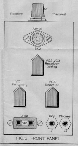
All parts should be measured carefully and holes drilled accordingly. There may well be slight differences between similar components and the drawings and layouts given should be used only as a guide. As an example of the exactness of layout The two capacitors VCI and VC4 just fit flush in the case specified. There is no room for any error at all since they are already flush up against the sides of the case and thus these components cannot be manipulated either way to correct for inaccuracies in holes already drilled.
The actual chassis was made from a piece of thin tinplate.
This material is used instead of the more usual aluminium because it can be cut to any shape or size with a pair of household scissors and is very easy to bend, while being already tinned components requiring to be earthed (grounded) can be soldered directly to it. If aluminium was used nuts, bolts. and tags would be required for this purpose
Note, do not make the chassis any deeper than 9/16 in. If you do, the result will be a midget station with the only minor drawback that it will be impossible to plug in the valves! You have been warned!!
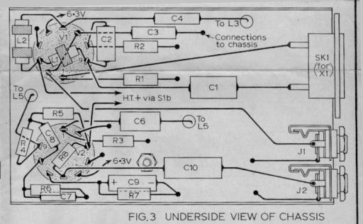
The holes for the two B9A valve holders (9 pin tube sockets for you Americans!) are cut first and a couple of holes drilled to allow leads to come up from below chassis. Next, complete all under chassis wiring prior to its insertion in the case as once this and the variable capacitors above chassis are wired there is, no way of getting at under chassis components again without unsoldering all the variables and removing both them and the valves in order to lift out the chassis
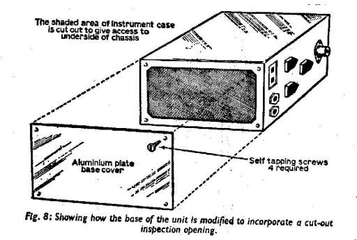
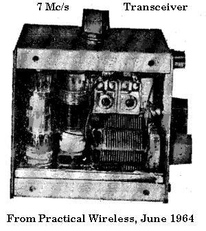
One interesting and very practical suggestion is that the bottom on the case should be removed and a small base-plate fitted. This would make inspection and servicing very much simpler - not to mention ease of construction. See Fig. 8. This is not done in the prototype and there may be some, who, for various reasons will not wish to cut a panel from the case. For the benefit of those the following tips are offered based on experience gained in wiring the original unit seen in the photograph.
First, wire the whole chassis, all leads from below chassis to anything above, i.e. p.a. tuning capacitor lead etc., should be wired and a long floating lead pushed through the appropriate hole. The green coil with reaction winding (Denco Range 4) may either be mounted by drilling a hole and using: the plastic locking nut supplied, or the method used in the original may appeal. A small scrap of tinplate is cut roughly to shape shown in Fig. 9. The core of the coil is removed and the thread for the plastic locking nut is cut off. The pointed end of the tinplate is then heated and pressed into the plastic end of the coil and allowed to cool and set. The coil can then be soldered via the piece of tinplate to the chassis. Note, the dust cores are removed from both coils.
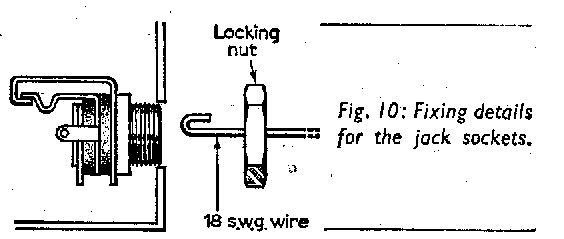
The crystal holder and the two jack plugs present a problem as once the chassis. is in place these three components are inside and have to be fixed from the outside. The jack sockets are "rescued" with a small piece of 18 s.w.g. wire bent as shown in Fig. 10. This was inserted into the hole in the "front panel", hooked on to the jack socket, and pulled. This exposed the threaded collar of the jack socket and the locking nut was then screwed on with tile other hand.
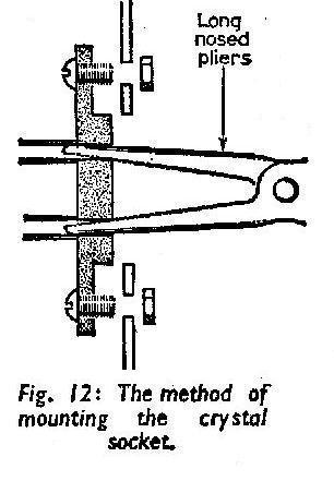
The crystal holder was a bigger problem, as there was no fixed threaded part which was itself connected to the component as in the case of the threaded collar on the jack sockets. In order to overcome this difficulty two bolts were inserted in the fixing holes in the crystal socket and were glued in place. When the glue was quite dry (24 hours to be certain) the socket was then wired into circuit and the chassis placed in the case. The jack sockets were then brought out as per the instructions given above. A pair of long-nosed pliers were then inserted into the actual crystal sockets and the whole assembly was pulled GENTLY into position. The two nuts were then screwed on with the free hand. (Fig. 12.)
No definite dimensions are given for the shield and mounting for the variable bandspread capacitor since these will vary depending on the component used. If a single capacitor is used instead of the bandpass arrangement shown, then the screen will not be necessary. In the prototype, the two bandset 300pF trimmers are mounted on one tin-plate shield and the aerial coil on the other. This latter coil is held in position by a piece of 18 s.w.g. wire from pins 1 and 9 and are earthed anyway. This coil and the trimmer or trimmers are wired up complete with tinplate screen, and the bandspread capacitors as one unit, prior to inserting the whole in the case.
POWER SUPPLY
On the roof of the case is a switch marked transmit/receive. It is either a single-pole two-way or a two-pole two-way.
One pole switches the aerial (antenna) to either the transmitter p.a. or to the receiver input, the use of the other pole is optional if a midget power unit is constructed using a TV pre-amplifier type transformer it must be noted that the maximum rating of these transformers is somewhere around 30mA. With both transmitter and receiver running, the drain on such a p.s.u. (P.S.) might well prove too great for the particular transformer and in such a case the other pole, S1b can be used to switch the h.t. to either valve, thus saving power. The power supply used on the original was capable of supplying l50 mA and the necessity did not arise. Incidentally, the average domestic valve radio will supply a convenient form of power, if a suitable plug or adapter is made. It would be even feasible to remove the output valve, plug in the rig in its place, and go on the air.
IMPORTANT! If you do use the power supply of a domestic receiver, first ascertain that the heater voltage is suitable - some radio sets have series connected heaters etc. It is imperative to check that the set is NOT an a.c./d.c. type, i.e. with mains directly connecting to one side of the chassis. It is equally important that if a midget p.s.u. is made that this is not an a.c./d.c. type either. One glance at the blueprint will show that the headphones would then be connected to one side of the mains as would the entire case, and this danger alone makes such a p.s.u. undesirable if not impracticable.
This point is mentioned at some length because in these days of miniaturisation it might prove a temptation to use just one tiny silicon diode in a half wave configuration for the h.t. line and do away with a comparatively bulky h.t transformer.
R.F. CHOKES
The two r.f. chokes in the transmitter circuit can be small standard components of any type that will fit in. In the prototype these were, in fact, derived from i.f. coils of the type originally intended for transistor sets, the associated capacitor and dust core being removed in each case. The first r.f. choke in the anode of the triode has one pie removed to avoid the possibility of parasitics. These converted i.f.'s have proved very efficient in this unusual role and stand up to the higher voltages applied to them.
The two midget jack plugs and sockets again originally favourites for transistor work appear to stand up satisfactorily to the tasks allotted them in the present design.
TRANSMITTER AERIAL CIRCUITS
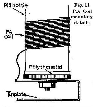
The p.a. coil will present no problems, being merely a length of wire wound on a 3/4 in. diameter coil former. The actual former used in the prototype was a pill bottle with a plastic top bolted to a piece of tinplate which was soldered directly to the chassis. However, 3/4 in. diameter formers (preferably ceramic) are available, which will save would-be constructors touring chemists shops (drugstores) with a ruler! The method of feeding the aerial from this coil is a matter of choice and will rather depend upon the aerial to be used.
If a dipole is available, then a link winding of some three turns should prove satisfactory, it being only necessary to adjust their position on the tank coil for correct loading and maximum output.
Aerial tuning units and lowpass filters are usually wired to accommodate a low impedance input, and again link coupling will serve.
If, on the other hand, a random length of wire, say, end-fed, is to be loaded up then it is possible to achieve this by tapping directly on the p.a. coil, the tap being varied up or down until a good match is secured. Once the correct tap has been located for a particular crystal and length of aeria1, it will not need to be varied. Thus, if, say, 40ft. of throw-out wire is loaded up then this could be carried in a small coil as a portable antenna.
A change of frequency, i.e. plugging in another crystal, will mean a change or tapping point on the p.a. coil. However, if two or three crystals are to be used and their frequencies are close together, then the same tap might be used with only slight loss of efficiency. The 40 metre band is only l00kc/s wide and of this 100 kc/s only the lower 50 kc/s are usually used for c.w. Suitable crystals for 7Mc/s are available very cheaply on the ex-government market, and these units are recommended for the transmitter described here.
TRANSMITTER TUNING
The transmitter may be tuned in a number of ways. By far the best method is to use a standing wave ratio (s.w.r.) meter to ensure that the last watt goes up the spout! For those not so equipped, the usual method of tuning for a dip on a meter in the p.a. anode may be used. Here, the mA meter may conveniently be plugged into the jack socket in place of the key for initial tuning up. The power input cannot be exactly calculated from this, because the meter will read not only the p.a. anode current, but p.a. screen and triode current as well. However. with the valve and h.t. used it is doubtful if one could violate the terms of the transmitting licence and exceed the permitted 150W for 7 Mc/s!!
RECEIVER TUNING
( The usual tuning procedure for regenerative circuits is used. For phone signals, the regeneration control is advanced to the point just before the detector starts to oscillate. For c.w. reception the control is adjusted just to the point of oscillation, turning it any further may result in lowered sensitivity.
FINAL REMARKS
The case is a steel case, and perhaps aluminium would be a more suitable choice. The steel case was a standard line, easily obtainable and was, therefore, chosen. Those who prefer aluminium could, perhaps, get a case made specially to their desired dimensions from any of the firms advertising such a service.

In the prototype, there is no form of ventilation and in view of the bulb temperature attained by miniature glass valves it is advised that a number of small holes, grouped in a neat pattern, be drilled in strategic places in the case: at the rear of the valves, low down near their bases, and immediately above them should suffice.
To use the station for other bands the appropriate coils in the Denco range should he used in place of those shown. The p.a. coil in the transmitter would require the number of turns to be varied accordingly, Suggested lines for experiment would be 45 turns for 3.5 Mc/s and 95 turns for l.8 Mc/s (fine wire). It is not suggested that the station be used on the higher bands due to the efficiency of the receiver decreasing with increased frequency.(Note: I believe the Denco coils may still be available from England - AF4K)
Again, it must be said, that we are DEEPLY grateful to PW Publishing Ltd. for the permission to reproduce this article and preserve it for nostalgia's sake!
Copyright PW Publishing Ltd., 1964. All Rights Reserved
 Back to the TOP
PLEASE: E-mail me now..

